


Votes - 1, Average rating: 4
(

 )
)
|
Photos and specs Smeg KR37X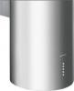 |


manual abstract
Accordingly, you may find descriptions of individual features that do not apply to your specific appliance. INSTALLATION • The manufacturer will not be held liable for any damages resulting from incorrect or improper installation. • The minimum safety distance between the cooker top and the extractor hood is 650 mm (some models can be installed at a lower height, please refer to the paragraphs on working dimensions and installation). • Check that the mains voltage corresponds to that indicated on the rating plate fixed to the inside of the hood. • For Class I appliances, check that the domestic power supply guarantees adequate earthing. Connect the extractor to the exhaust flue through a pipe of minimum diameter 120 mm. The route of the flue must be as short as possible. • Do not connect the extractor hood to exhaust ducts carrying combustion fumes (boilers, fireplaces, etc.). • If the extractor is used in conjunction with non-electrical appliances (e.g. gas burning appliances), a sufficient degree of aeration must be guaranteed in the room in order to prevent the backflow of exhaust gas. The kitchen must have an opening communicating directly with the open air in order to guarantee the entry of clean air. USE • The extractor hood has been designed exclusively for domestic use to eliminate kitchen smells. • Never use the hood for purposes other than for which it has been designed. • Never leave high naked flames under the hood when it is in operation. • Adjust the flame intensity to direct it onto the bottom of the pan only, making sure that it does not engulf the sides. • Deep fat fryers must be continuously monitored during use: overheated oil can burst into flames. • Do not flambe under the range hood; risk of fire • This appliance is not intended for use by persons (including children) with reduced physical, sensory or mental capabilities, or lack of experience and knowledge, unless they have been given supervision or instruction concerning use of the appliance by a person responsible for their safety. • Children should be supervised to ensure that they do not play with the appliance. MAINTENANCE • Switch off or unplug the appliance from the mains supply before carrying out any maintenance work. • Clean and/or replace the Filters after the specified time period (Fire hazard). • Clean the hood using a damp cloth and a neutral liquid detergent. The symbol A on the product or on its packaging indicates that this product may not be treated as household waste. Instead it shall be handed over to the applicable collection point for the recycling of electrical and electronic equipment. By ensuring this product is disposed of correctly, you will help prevent potential negative consequences for the environment and human health, which could otherwise be caused by inappropriate waste handling of this product. For more detailed information about recycling of this product, please contact your local city office, your household waste disposal service or the shop where you purchased the product. EN 13 CHARACTERISTICS Dimensions Min. Min. 550mm 550mm Components Ref. Q.ty Product components 1 1 Hood equipped with: Controls, Lights, Filters 3 1 Hood support equipped with the Exhaust Group 7 1 tube in PVC 8 1 Directioned grid 8c 1 Air outlet reduction 0 120mm 9 1 Reduction flange 0 150-120 mm Ref. Q.ty Installation components 11 4 Small blocks 0 10 12a 4 Screws 5 x 70 12b 4 Screws M4 x 15 12e 2 Screws 2,9 x 9,5 13 4 Screws plug M4 Q.ty Documentations 1 Instruction booklet EN 14 INSTALLATION Wall drilling and bracket fixing When installing the hood in recycling version it has to be taken into consideration that space remaining between the hood and the upper limit (ceiling or self) is at least 8-10 cm. On the wall, draw: • a Vertical line up to the ceiling or upper limit, at the centre of the area in which the hood is to be fitted; • a Horizontal line at a minimum of 1050 mm above the Cooker Top; . • As indicated, mark a reference point at 100 mm to the right of the vertical reference line. • Repeat this operation on the other side, checking that the two marks are level. • As indicated, mark a reference point at 390 mm above the horizontal reference line, and at 100 mm to the right of the vertical reference line. • Repeat this operation on the other side, checking that the two marks are level. • Drill at the points marked, using a 0 10 mm drill bit. • Insert the plugs 11 into the holes. EN 15 Hood support mounting Lean the hood support 3 against the wall making sure that holes in the hood support correspond to those in the wall. Block the hood support to the wall using 4 12a (5 x 70) screws supplied with the hood. Before fastening the screws definitively make sure that the support is well-levelled. Only after this operation proceed with the definitive tightening of the screws. _Air outlet connection in the ducting version_ When installing the hood in ducting ver...