


Votes - 1, Average rating: 3
(

 )
)
|
Photos and specs Yamaha NS-C500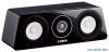 |


manual abstract
If you wish to discard these items, please contact your local authorities or dealer and ask for the correct method of disposal. 2 En CONTENTS CONTENTS PLACING THE SPEAKER please refer to the owner’s manual that came with the YTSF500/ T500. 290 mm (11-3/8") English SUPPLIED ACCESSORIES ............................3 Place the speaker on a TV rack or other stable surface, and place it just under the center of the TV or screen. PLACING THE SPEAKER ..............................3 Presence Subwoofer CONNECTING TO YOUR AMPLIFIER ...........4 Front ATTACHING THE GRILLES ...........................5 SPECIFICATIONS ...........................................5 Surround back NS-C500 Center Surround 95 mm(3-3/4") Insert screws “D (M6 x 16)” that came with the YTS-F500/T500 into the screw holes. Rear view NS-C500 Use speaker bracket “B” that came with the YTS-F500/T500. NS-C500 (Installation example using YTS-F500) SUPPLIED ACCESSORIES After unpacking, make sure that the following accessories are included. Grille (x2) The grilles are detached from the speaker and packed separately. Be careful not to lose them. Notes • To avoid accidents resulting from tripping over loose speaker cable, affix them securely to the wall. • Secure placement and installation is the owner’s responsibility. YAMAHA shall not be liable for any accident caused by improper placement or installation of speakers. • Placing the speakers too close to a CRT-type TV may impair the picture color or cause a buzzing noise. In this case, move the speakers away from the TV. This is not an issue with LCD and plasma TVs. ¦ Mounting the speaker on the Yamaha YTS-F500/T500 TV stand You can use the screw holes [diameter: 6 mm (1/4"), hole depth: 16 mm (5/8")] on the rear of this unit to mount the speaker on the YTS-F500/T500. For installation details, Notes • Do not install the speaker on a wall using nails, adhesives, or any other unstable hardware. Long term use and vibration may cause it to fall. • Be careful not to pinch the speaker cables between the speaker and the speaker bracket or speaker stand. • Do not lean or place any object on the speaker. Otherwise, the TV stand bracket may be deformed. 3 En CONNECTING TO YOUR AMPLIFIER CONNECTING TO YOUR AMPLIFIER Before making connections, make sure that the amplifier is switched off. Standard connections CENTER Loosen Tighten Black (–) Insulation coating Red (+) Bare wire Amplifier or Receiver Speaker output terminals NoteDo not insert the insulation into the hole. If the connections are faulty, you will hear no sound from the speaker. NS-C500 Rear view ¦ When connecting the speaker cable ¦ When using a banana plug • Do not let the bare speaker wires touch each other as this could damage the speaker or the amplifier. Banana plug • Make sure you connect the speakers with the correct polarity—positive (+) terminals to positive (+) terminals, and negative (–) terminals to negative (–) terminals. If you get them crossed over, the sound will be unnatural and lack bass. • Please refer to the owner’s manual that came with your amplifier or receiver. ¦ How to connect the speaker cables 1. Loosen the terminal knob. 2. Remove 10 mm (3/8") of insulation from each end of the 1. Tighten the terminal knob. cables, and twist the exposed conductors together neatly 2. Simply insert the banana plug into the terminal. and tightly, as shown below. 10 mm (3/8") Good No Good 3. Insert the bare wire. 4. Tighten the knob and secure the cable. 5. Test the firmness of the connection by pulling lightly on the cable at the terminal. Note When using an amplifier with a rated output power higher than the nominal input power of the speaker, care should be taken never to exceed the speaker’s maximum input. 4 En ATTACHING THE GRILLES ATTACHING THE GRILLES SPECIFICATIONS The speaker and the grilles are packed separately. To attach the grilles, line up the projections (magnets) on the reverse side of each grille with their corresponding screw heads on the speaker. Notes • When removing the grilles, be careful not to touch the drive units, and not to exert excessive force with any tools. • Do not touch or apply impact to the speaker’s diaphragm. Otherwise, the speaker may malfunction. • There are magnets on the reverse side of the grille. Do not place the grille close to objects that might be affected by magnets, such as CRT TV, clock, magnetic card, diskette, etc., after removing it. Type ............... 2-way acoustic suspension speaker system Non-Magnetic shielding type Driver ............................. 12 cm (4-3/4") cone woofer . 2 Advanced PMD 3 cm (1") aluminum dome tweeter DC diaphragm Impedance .................................................................. 6 . Frequency Response .............. 55 Hz to 50 kHz (–10 dB) 100 kHz (–30 dB) Nominal Input Power ............................................. 40 W Maximum Input Power .........................................160 W Sensitivity ............................................... 87 ...