


Votes - 1, Average rating: 5
(
 )
)
)
|
Photos and specs Makita 6823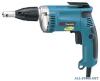 |


manual abstract
17. Do not use tool if switch does not turn it on or off. Any tool that cannot be controlled with the switch is dangerous and must be repaired. 18. Disconnect the plug from the power source before making any adjustments, changing accessories, or storing the tool. Such preventive safety measures reduce the risk of starting the tool accidentally. 19. Store idle tools out of reach of children and other untrained persons. Tools are dangerous in the hands of untrained users. 20. Maintain tools with care. Keep cutting tools sharp and clean. Properly maintained tools with sharp cutting edges are less likely to bind and are easier to control. 21. Check for misalignment or binding of moving parts, breakage of parts, and any other condition that may affect the tools operation. If damaged, have the tool serviced before using. Many accidents are caused by poorly maintained tools. 22. Use only accessories that are recommended by the manufacturer for your model. Accessories that may be suitable for one tool, may become hazardous when used on another tool. SERVICE 24. When servicing a tool, use only identical replacement parts. Follow instructions in 23. Tool service must be performed only by the Maintenance section of this manual. qualified repair personnel. Service or main- Use of unauthorized parts or failure to follow tenance performed by unqualified personnel Maintenance instructions may create a risk of could result in a risk of injury. electric shock or injury. USE PROPER EXTENSION CORD: Make sure your extension cord is in good condition. When using an extension cord, be sure to use one heavy enough to carry the current your product will draw. An undersized cord will cause a drop in line voltage resulting in loss of power and overheating. Table 1 shows the correct size to use depending on cord length and nameplate ampere rating. If in doubt, use the next heavier gage. The smaller the gage number, the heavier the cord. Table 1: Minimum gage for cord Ampere Rating Volts Total length of cord in feet 120 V 25 ft. 50 ft. 100 ft. 150 ft. More Than Not More Than AWG 0 6 18 16 16 14 6 10 18 16 14 12 10 12 16 16 14 12 12 16 14 12 Not Recommended SPECIFIC SAFETY RULES USB004-2 DO NOT let comfort or familiarity with product (gained from repeated use) replace strict adherence to screwdriver safety rules. If you use this tool unsafely or incorrectly, you can suffer serious personal injury. 1. Hold tool by insulated gripping surfaces 3. Hold the tool firmly. when performing an operation where the 4. Keep hands away from rotating parts. cutting tool may contact hidden wiring or its own cord. Contact with a “live” wire will 5. Do not touch the bit or the workpiece make exposed metal parts of the tool “live” immediately after operation: they may be and shock the operator. extremely hot and could burn your skin. 2. Always be sure you have a firm footing. Be sure no one is below when using the tool in high locations. SAVE THESE INSTRUCTIONS SAVE THESE INSTRUCTIONS WARNING: MISUSE or failure to follow the safety rules stated in this instruction manual may cause serious personal injury. SYMBOLS USD201-2 The followings show the symbols used for tool. V .......................volts n....................no load speed ° A ....................... amperes ....................Class II Construction Hz ..................... hertz .../min................revolutions or reciprocation per minute ................ alternating current FUNCTIONAL DESCRIPTION FUNCTIONAL DESCRIPTION 1. Locking sleeve A B 1 002619 11mm (3/64") 1. Locater 002620 11mm (3/64") 1. Locater 002628 1 2 1. Switch trigger 2. Lock button CAUTION: • Always be sure that the tool is switched off and unplugged before adjusting or checking function on the tool. Depth adjustment The depth can be adjusted by turning the locking sleeve. Turn it in “A” direction for less depth and in “B” direction for more depth. One full turn of the locking sleeve equals 1.5 mm (1/16”) change in depth. Adjust the locking sleeve so that the distance between the tip of the locator and the screw head is approximately 1 mm (3/ 64”) as shown in the figures. Drive a trial screw into your material or a piece of duplicate material. If the depth is still not suitable for the screw, continue adjusting until you obtain the proper depth setting. Switch action CAUTION: • Before plugging in the tool, always check to see that the switch trigger actuates properly and returns to the “OFF” position when released. To start the tool, simply pull the switch trigger. Tool speed is increased by increasing pressure on the switch trigger. Release the switch trigger to stop. A A Hook For continuous operation, pull the switch trigger and then push in the lock button. To stop the tool from the locked position, pull the switch trigger fully, then release it. NOTE: • Even with the switch on and motor running, the bit will not rotate until you fit the point of the bit in the screw head and apply forward pressure to engage the clutch. 00...
Other models in this manual:Power Screwdrivers and Drills - 6824 (89.18 kb)
Power Screwdrivers and Drills - 6825 (89.18 kb)