


Votes - 2, Average rating: 4
(

 )
)
|
Photos and specs Shindaiwa 357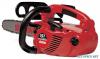 |


manual abstract
Low depth gauge CHN-05 Cause Wrong gauge setting or no gauge used. Result Rough cutting. Chain grabs. Saw won’t pull chain through wood. Excessive wear on the cutter heel. Remedy If depth gauges are too low, the chain is no longer serviceable. 32 9 DESCRIPTIONMAINTENANCE DESCRIPTIONMAINTENANCE Additional Safety Precautions (cont.) WARNING! ¦ Install the appropriate guide-bar scabbard before transporting the saw. ¦ Never operate a saw that is damaged, improperly adjusted, or not completely and securely assembled. ¦ Use only Shindaiwa-recommended parts when repairing or servicing this saw. ¦ Do not use this saw if the saw chain continues to move after the throttle control trigger is released. ¦ Use extra care when cutting a limb that is under tension! A limb under tension could spring back suddenly, causing you to lose control of the saw! ¦ Use extreme caution when cutting smaller brush and saplings! Small- diameter material may catch in the chain and be whipped toward you or pull you off balance, causing you to lose control of the saw! ¦ Operate the saw only in a well ventilated area. ¦ Keep the saw handles dry, clean and free of oil or fuel mixture. ¦ Never operate any saw while in a tree unless you have been specifically trained to do so! ¦ Never perform service or repairs to this saw unless you are specifically trained and equipped to do so! ¦ Improper maintenance, use of nonconforming replacement components, or the removal of safety devices, such as the chain brake or any of the chain brake components, could result in serious injury. ¦ Never allow any part of your body near the clutch cover of an operating saw. ¦ Never operate a saw with damaged or missing anti-vibration cushions. Long-term exposure to vibration can damage your hands. ¦ Always maintain a firm footing while operating this saw! Ladders and other temporary platforms can shift unexpectedly, and are not recommended! Sharpening the Chain Sharpening Technique 1. Using a 5/32" round file, sharpen all cutters to a 30° angle . IMPORTANT! File all cutters to the same angle and depth! Unequal filing may cause the saw to vibrate or cut erratically! NOTE: For consistent filing angles, use a filing guide such as Oregon. p/n 37534 or equivalent. Using a filing gauge CHN-19 Using a flat file to round the front corner on a depth gauge CHN-18Using a depth gauge joiner 2. After all cutters are sharpened, use a depth gauge joiner (Oregon. p/n 106738 or equivalent) to measure the height of each depth gauge. 3. As required, lower the depth gauges to a height of 0.020" (0.5 mm). Use a flat file; Oregon p/ n 12211 or equivalent. 4. After all depth gauges have been adjusted, use a flat file to round each depth gauge leading edge to its original curvature and angle. Saw Chain Installing and Adjusting the Guide Bar and Saw Chain CHN-09 35707 1. Remove the clutch cover nuts. 35705 35706 3. Remove the clutch cover PRESS DOWN 2. Unhook the brake lever support arm. a b Pull back ASSEMBLY MAINTENANCE 1.2. 3.4. Your saw’s performance on the job depends greatly on the condition of its saw chain. How the saw chain works As the chain is pulled through the wood: 1. The depth gauge determines the depth of cut for the cutter. 2. The cutter’s leading edge enters the wood, causing the entire cutter to “rock back” and lift away from the bar. 3. The top plate peels the severed wood chip away. 4. The chip is discharged out the rear of the cutter. IMPORTANT! Most of the actual cutting is done by the sides and corners of the individual cutters. IMPORTANT! The chain brake must be completely disengaged before removing or installing the clutch cover! 1. Use the 13 mm socket wrench to remove the clutch cover nuts. Turn the nuts counter-clockwise to remove. 2. Slide the rubber stopper downward and unhook the support arm from the brake lever (see illustration below). Stopper 3. Disengage the clutch cover retaining hook by pressing the cover as shown, and then remove the clutch cover. 4. Remove and discard the packing spacer. 5. Place the guide bar over the guide bar studs and chain tensioner pin. If necessary, turn the chain tension screw in or out until the loop slips easily over the guide bar tip. Continued on next page. ASSEMBLY35708 57704 Brake lever support arm 4. Remove the packing spacer. 5. Install the guide bar. WARNING! Never start the engine without the clutch cover installed! 35709 6. Install the chain loop. CHN-14 BAR TIP Top of Bar Bottom of Bar 7. Install the clutch cover over the two bar studs, and then engage the brake lever and support arm. Install the two 13 mm bar nuts and tighten finger-tight only. CAUTION! Failure to align the guide bar and chain tensioner pin as shown can cause serious damage to the clutch cover, guide bar, tensioner pin and/or engine crankcase! ASSEMBLY35708 57704 Brake lever support arm 4. Remove the packing spacer. 5. Install the guide bar. WARNING! Never start the engine without the clutch cover installed! 35709 6. Install the chain loop. CHN-14 ...
Other models in this manual:Chainsaws - 35701 (444.27 kb)
Chainsaws - 72362-93115 (444.27 kb)