


Votes - 4, Average rating: 3.8
(

 )
)
|
Photos and specs Pioneer DEH-2200UBB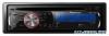 |


Other manuals for this model:
Car Receivers - DEH-2200UBB (2 mb)
Car Receivers - DEH-2200UBB (509.93 kb)
manual abstract
(При установке рамки ее сторона с канавкой должна быть на-правлена вниз.) Декоративная рамка • Снятие передней панели облегчает доступ к декоративной рамке. Ru This product 4 Note: Depending on the kind of vehicle, the function of 2* and 4* may be different. In this case, be sure to connect 1 * to 4* and 3* to 2*. Antenna jack 14 Rear output 19 To Rear output I r J 21 Power amp (sold separately) L _ Fuse (10 A) Wired remote input Hard-wired remote control adaptor can be connected (sold separately). Connect leads of the same color to each other. Qfi Yellow (2*) Back-up (or accessory) Yellow (1*) Connect to the constant ' supply terminal. 2 V Red (4*) Accessory (or back-up) 10 Red (3*) Connect to terminal controlled by ignition switch (12 V DC). Black (chassis ground) Connect to a clean, paint-free metal location, 12 ISO connector In some vehicles, the ISO connector may be divided into two. In this case, be sure to connect to both connectors. 13 Speaker leads White: Front left © White/black: Front left © Gray: Front right © Gray/black: Front right © Green: Rear left © Green/black: Rear left © Violet: Rear right © Violet/black: Rear right © 15 Yellow/black If you use an equipment with Mute function, wire this lead to the Audio Mute lead on that equipment. If not, keep the Audio Mute lead free of any connections. / _ 16 Blue/white Connect to system control terminal of the power amp (max. 300 mA 12 V DC). 17 Blue/white (6*) Connect to auto-antenna relay control terminal (max. 300 mA 12 V DC). 18 Blue/white (5*) The pin position of the ISO connector will differ depending on the type of vehicle. Connect 5* and 6* when Pin 5 is an antenna control type. In anothertype of vehicle, never connect 5* and 6*. 20 Connect with RCA cables (sold separately) 22 System remote control 25 Rear speaker 23 Left 1 1 24 Right I [\®J + e 25 Rear speaker , \ 26 Perform these connections when using the optional amplifier. Fig. 1 Abb. 1 Afb. 1 Pmc. 1 En En (Connections j ( ) Important • When installing this unit In a vehicle without an ACC (accessory) position on the Ignition switch, failure to connect the red cable to the terminal that detects operation of the Ignition key may result In battery drain. ACC position No ACC position • Use of this unit In conditions other than the following could result In fire or malfunction. — Vehicles with a 12-volt battery and negative grounding. — Speakers with 50 W (output value) and 4 ohm to 8 ohm (Impedance value). • To prevent a short-circuit, overheating or malfunction, be sure to follow the directions below. — Disconnect the negative terminal of the battery before Installation. — Secure the wiring with cable clamps or adhesive tape. Wrap adhesive tape around wiring that comes Into contact with metal parts to protect the wiring. — Place all cables away from moving parts, such as the gearshift and seat rails. — Place all cables away from hot places, such as near the h...
Other models in this manual:Car Receivers - DEH-2200UB (836.06 kb)
Car Receivers - DEH-2220UB (836.06 kb)